High resolution extended image near field
optics:
2. An idealised symmetric extended image
near field imaging device
[this page | pdf | references | back links]
Copyright (c) Malcolm
Kemp 2010
Return
to Abstract and Contents
Next
page
Consider a rotationally symmetric optical layout with an
(axial) cross-section as per Figure 1. This consists of two large highly
elongated truncated ellipsoidal mirrors, with plane mirrors (perpendicular to
the axis of rotation) placed at the left and right hand ends of the
arrangement. The centre of the mirror at the left hand end of the layout,  , is one of
the focal points of the ellipsoid that forms the left half of the layout. The
centre of the mirror at the right hand end of the arrangement,
, is one of
the focal points of the ellipsoid that forms the left half of the layout. The
centre of the mirror at the right hand end of the arrangement,  , is one of
the focal points of the ellipsoidal mirror that forms the right half of the
layout. Both ellipsoidal mirrors also share a focal point at
, is one of
the focal points of the ellipsoidal mirror that forms the right half of the
layout. Both ellipsoidal mirrors also share a focal point at  , half-way
along the layout (i.e. the two ellipsoidal mirrors are confocal).
, half-way
along the layout (i.e. the two ellipsoidal mirrors are confocal).  forms a
straight line, so the ellipsoidal mirrors are also coaxial.
forms a
straight line, so the ellipsoidal mirrors are also coaxial.
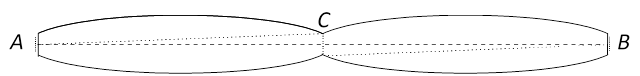
Figure 1: A large highly elongated symmetric truncated
confocal and coaxial ellipsoidal mirror pair, with plane mirrors perpendicular
to the axis of rotation at each end of the layout
Suppose that:
(a) The plane
mirrors at each end of the layout are thin ‘nearly fully silvered’ idealised
reflectors (with the silvering pointing inwards, i.e. in each case towards ), i.e. they
transmit a small fraction of light incident on them but otherwise perfectly
reflect all of the light incident onto them);
(b) Both ellipsoidal
mirrors are ‘partly silvered’ idealised reflectors, i.e. perfectly reflect a
proportion of all of the light incident onto them. It is assumed that behind
them is a perfect absorber, so that any light transmitted through them can be
ignored. The extent to which they need to be partially rather than fully
silvered depends on the extent to which light that has bounced back and forth
between the plane mirrors would corrupt the image formation. Image blurring
arising because of these path trajectories can be eliminated by making the
ellipsoidal mirrors only slightly mirrored, but at the expense of less light
being available to create the image;
(c) All four mirrors
are many wavelengths in size;
(d) The ellipsoidal
mirrors are arbitrarily elongated (so the angle subtended by the hole at on either or is
arbitrarily small);
(e) A flat object is
placed a small fraction of a wavelength to the left of ; and
(f) The object
, whilst many wavelengths in size, is only an arbitrarily small fraction of the
size of the entire aperture formed by the rim of the truncated ellipsoidal
mirror (so is not drawn to scale in Figure 1).
What image of the object in (e) would be formed a small
fraction of a wavelength to the right of ?
In the absence of the two end plane mirrors, the
ellipsoidal mirror pair form an aplanatic layout, with object and image planes
at and respectively.
We would therefore expect it to create a clean, but Rayleigh
resolution-limited, image at of the object placed at in a manner
similar to any other ‘conventional’ imaging arrangement. For the image not to
suffer material amounts of spherical aberration, we need the object to be small
relative to the distance between the focal point and the nearest rim of the
ellipsoidal mirror, but given design feature (e) the object could still be many
wavelengths in size before this became an issue. Objects placed a sufficiently
small fraction of a wavelength behind at would
therefore form an image a sufficiently small fraction of a wavelength behind that is
arbitrarily close in form to a conventional Rayleigh resolution-limited image.
However, there are three ways in which the complete layout
described in this hypothetical situation differs from that a ‘conventional’
imaging arrangement:
(i) The
nearly fully silvered plane mirror at the right hand end of the layout converts
the device from a far-field to a near-field device. There is now an
active part of the device near to, indeed exactly in the image plane;
(ii) The layout
subtends a solid angle onto the image plane at that is
almost the maximum possible onto a plane. The only rays that are missing from
the complete span of possible ray trajectories are ones that would otherwise
have been coming from the vicinity of .
Design feature (d) means that these form an arbitrarily small proportion of the
total angle span onto the image plane and so in the limit can be ignored; and
(iii) The nearly fully
silvered plane mirror at the left hand end of the layout constrains the nature
of the light waves entering the cavity formed by the ellipsoidal mirrors, and
thus also constrains the nature of the waves converging onto the image plane.
Our assertion is that inclusion of these non-standard
aspects to the layout result in an image of being
formed at that is no longer subject to
the Rayleigh resolution limit. Indeed the image should be arbitrarily
accurate, to the extent that it is possible to create such an idealised layout
in practice. Moreover, if the plane mirrors are sufficiently close to being
fully silvered as per design feature (a), then the device would create an extended
image that circumvents the Rayleigh resolution limits that might make SNOM-type
technology more commercially viable.
Readers may, however, object that, even if this assertion
were true, the design features needed for the above device to work would
involve some carefully crafted limiting properties. Some of these relate to the
physical characteristics of the materials used to make the mirrors, some relate
to the dimensions of the layout (both width and length) relative to the object
being imaged and some relate to the proportion of light leaving the object that
is reconstituted to form the image. Moreover, with the above design the object
and image are of the same size, limiting the practical usefulness of the
proposed design for microscopy and certainly rendering it useless for
telescopy.
The main aim of discussing the above layout is thus to
elucidate the principles involved and to suggest ways in which the layout would
need to be refined were it to be applied in practice.
NAVIGATION LINKS
Contents | Prev | Next