Solar-powered space flight
7b. Achieving the desired level of
optical precision: Mathematical analysis
[this page | pdf | references | back links]
Return to Abstract
and Contents
Next page
7.4 We analyse
further point (d) as follows. Assume that the mirror is rotating around its
axis of symmetry (the x-axis) with an angular speed  and the mirror is
described as a surface using cylindrical polar coordinates
and the mirror is
described as a surface using cylindrical polar coordinates  where
where  ,
,  .
.
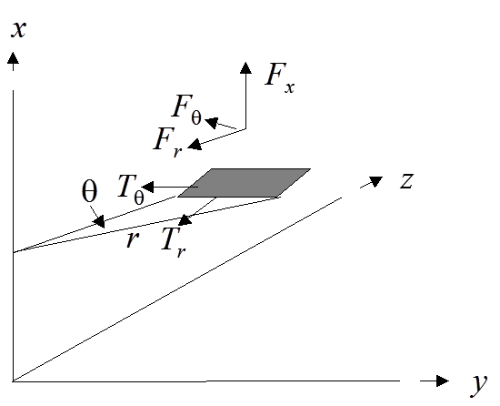
We first consider the
situation where there are many stanchions suitably positioned so that each part
of the mirror is subject to a force from them per unit mirror area
(cross-sectional area perpendicular to the x-axis) of  . We assume initially
that these forces are continuously distributed, although of course in practice
there would be a finite (albeit possibly quite large) number of stanchions, so
we would merely have a discrete approximation to this continuous ideal. Assume
that the corresponding tensions within the mirror (per unit cross-sectional
area) are
. We assume initially
that these forces are continuously distributed, although of course in practice
there would be a finite (albeit possibly quite large) number of stanchions, so
we would merely have a discrete approximation to this continuous ideal. Assume
that the corresponding tensions within the mirror (per unit cross-sectional
area) are  in the plane of the
mirror, see Figure 12.
in the plane of the
mirror, see Figure 12.
Figure 12. Forces on a
small part of the larger mirror
In the absence of thrust,
the vehicle would be in free-fall. If in addition  and
and  then there would be
no tension within the mirror and it would be completely floppy. If we assume as
above that the vehicle ejects propellant along the positive x-axis and
if we arrange for
then there would be
no tension within the mirror and it would be completely floppy. If we assume as
above that the vehicle ejects propellant along the positive x-axis and
if we arrange for  then all of the forces
on the mirror are rotationally symmetric. We could in principle have the mirror
made up of several concentric annuli with transmission mechanisms between them
that allow different annuli to rotate at different speeds, but this would add
complexity and mass to the overall arrangement, so we assume that is constant for all
then all of the forces
on the mirror are rotationally symmetric. We could in principle have the mirror
made up of several concentric annuli with transmission mechanisms between them
that allow different annuli to rotate at different speeds, but this would add
complexity and mass to the overall arrangement, so we assume that is constant for all  although
not necessarily constant for all
although
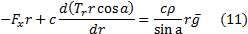
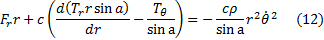
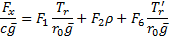
not necessarily constant for all  . The equations of
motion satisfied by the mirror therefore become:
. The equations of
motion satisfied by the mirror therefore become:
We first note that
ideally we would have constant ratios between  ,
,  ,
,  and
and  for all (and
hence we would have the angle,
for all (and
hence we would have the angle,  , that each stanchion
would make to the x-axis, were there to be merely one stanchion for each
mirror element, also independent of ). This can be
achieved by keeping
, that each stanchion
would make to the x-axis, were there to be merely one stanchion for each
mirror element, also independent of ). This can be
achieved by keeping  proportional to
  , i.e.
  constant,
perhaps by ejecting a small proportion of the propellant in a manner (e.g. in
the
constant,
perhaps by ejecting a small proportion of the propellant in a manner (e.g. in
the  direction) that
creates a torque, that when transmitted to the mirror increases or reduces its
rotational speed.
direction) that
creates a torque, that when transmitted to the mirror increases or reduces its
rotational speed.
We next note that it is
possible to come up with plausible arrangements that do potentially keep the
mirror tensioned in the manner indicated above. Reverting to the iterative
notation used previously, focusing on the part of the mirror where  is positive (and
starting at 1), and scaling the overall mirror size so that its overall radius
is
is positive (and
starting at 1), and scaling the overall mirror size so that its overall radius
is  we have:
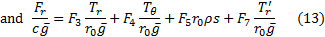
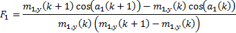
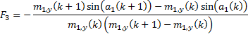
where:


NAVIGATION LINKS
Contents | Prev | Next