Solar-powered space flight
5b. Creating ultra-lightweight solar
power concentrators: Rotationally symmetric aplanatic two mirror arrangements
[this page | pdf | references | back links]
Return to Abstract
and Contents
Next page
5b. Rotationally
symmetric aplanatic two mirror arrangements
5.5 We
concentrate on rotationally symmetric aplanatic two mirror arrangements as
certain of these exhibit all of the above characteristics. For those readers
not familiar with optical theory, ‘aplanatic’ in this context in effect means
‘creates a sharp focus’. Optical theory requires aplanatic arrangements
involving strong magnification over a wide range of angles to have layouts that
satisfy the so-called sine criterion, see Klein and
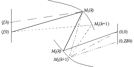
Furtak (1986). The cross-sections can be iteratively determined as follows,
see also Figure 7:
(a) At the k
’th iteration, a light ray starting at exactly the object point,  , should go through
the image point,
, should go through
the image point,  , after striking the
first mirror at
, after striking the
first mirror at  and the second
mirror at
and the second
mirror at  , say.
(b) We arrange for  both to lie on the
tangent to and if a light ray
starts at
both to lie on the
tangent to and if a light ray
starts at  , strikes the first
mirror at and the second
mirror at for the ray then to
pass through
, strikes the first
mirror at and the second
mirror at for the ray then to
pass through  ,
,  small (positive or
negative). We identify the position of
small (positive or
negative). We identify the position of  in a like fashion
but so that if a light ray starts at , strikes the first
mirror at and the second
mirror at then it passes
through . In the limit as
in a like fashion
but so that if a light ray starts at , strikes the first
mirror at and the second
mirror at then it passes
through . In the limit as  , the layout is then
image forming and if the correct choice of
, the layout is then
image forming and if the correct choice of  is made (see later)
then the mirror pair is aplanatic (of order 1).
is made (see later)
then the mirror pair is aplanatic (of order 1).
Figure 7. Schematic
diagram illustrating derivation of mirror pair cross-sections
5.6 This can be
mathematically re-expressed as follows, see Kemp (2001) and Kemp (2003). We
have for  :
:

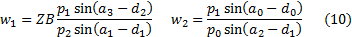
As the light rays are
being deflected by reflection, we also have for  :
:
We choose seed values of  and
and  (for )
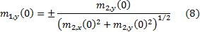
so that the resulting mirror layout satisfies the sine criterion. For a far
away source (e.g. f = –109) we can without loss of generality set
(for )
so that the resulting mirror layout satisfies the sine criterion. For a far
away source (e.g. f = –109) we can without loss of generality set  . The sine criterion
is then satisfied if:
. The sine criterion
is then satisfied if:
We can iterate either
from shallower angles to more oblique angles, or vice versa. We can switch
between the two by using as seed values later iterated results and reversing
the sign of . So without loss of
generality (and if we wish to have the maximum possible angle span) we can
iterate from highly oblique angles, choosing  equal to a small
number close to zero, say 10-9, and choosing
equal to a small
number close to zero, say 10-9, and choosing  and
and  , where
  and
and  are arbitrary real
numbers (positive or negative). Then we need
are arbitrary real
numbers (positive or negative). Then we need  for the initial
parameters to satisfy the sine criterion. Without loss of generality we can
choose
for the initial
parameters to satisfy the sine criterion. Without loss of generality we can
choose  . Given these initial
seed conditions different layouts arise depending on whether is
positive or negative. The choice of the sign of is
made so that the sine criterion remains satisfied as
. Given these initial
seed conditions different layouts arise depending on whether is
positive or negative. The choice of the sign of is
made so that the sine criterion remains satisfied as  changes.
Only one choice will work depending on the layout, and, given the conventions
we have adopted above by choosing , the correct choice
seems to be
changes.
Only one choice will work depending on the layout, and, given the conventions
we have adopted above by choosing , the correct choice
seems to be 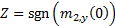 .
.
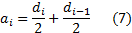
We iteratively update the
values of  as follows for a
small :
as follows for a
small :
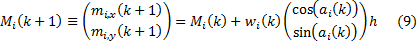
where as deflection
occurs by reflection:
We end the iteration no
later than when light rays cease to be able to pass freely through the mirror
arrangement, once the cross-sections have been rotated around the x-axis
to produce the complete three-dimensional mirror surfaces.
5.7 Each of the
signs of , and can
be either positive or negative leading to 8 possible two mirror layouts. In 6
of the 8 cases there is a discontinuity in the feasible angle ranges of rays
striking the image plane when we change the value of  from slightly below
1 to slightly above 1, see Kemp (2003).
Thus there are 14 possible overall layout types, whose optical characteristics
can be summarised for our purposes by the following metrics:
from slightly below
1 to slightly above 1, see Kemp (2003).
Thus there are 14 possible overall layout types, whose optical characteristics
can be summarised for our purposes by the following metrics:
(a) effective
aperture area factor = area of first mirror perpendicular to sun's rays,
expressed as a proportion of the maximum possible were the angle span of rays
falling onto the image plane to be the complete range from wholly oblique to
exactly perpendicular to the image plane. The higher this is, the closer to the
thermodynamic upper temperature limit such a concentrator can approach.
(b) mirror surface area
factor = the total surface area of the two mirrors combined as a multiple
of the effective aperture area. The closer this is to 1, the less is the mirror
surface area required per unit of power delivered, and therefore the higher the
power per unit mass that the concentrator can deliver.
(c) aberration
factor = average maximum second order aberration for sunlight in the
vicinity of the earth (i.e. for a far away source subtending approximately a
semi angle of 0.267°). The lower this is, the closer the mirror pair can get to
the thermodynamic upper limit when concentrating sunlight without resorting to
off-axial adjustments, see Kemp (2001).
NAVIGATION LINKS
Contents | Prev | Next